Discutez avec notre équipe de direction avant votre départ
Our Managing Team
Avant de partir, nous vous invitons à vous entretenir directement avec notre équipe de direction afin de bénéficier des conseils techniques les plus précis, d’un accompagnement en matière de tarification et des options de personnalisation les mieux adaptées à votre projet. Nos experts peuvent rapidement évaluer vos besoins, vous recommander des solutions de filtres en plastique fritté adaptées et vous aider à réduire les risques liés à l’approvisionnement tout en améliorant l’efficacité, la cohérence et la stabilité à long terme de votre approvisionnement pour vos applications industrielles.
Vous avez besoin d'aide pour choisir la cartouche filtrante adaptée ?
Our Sales Team
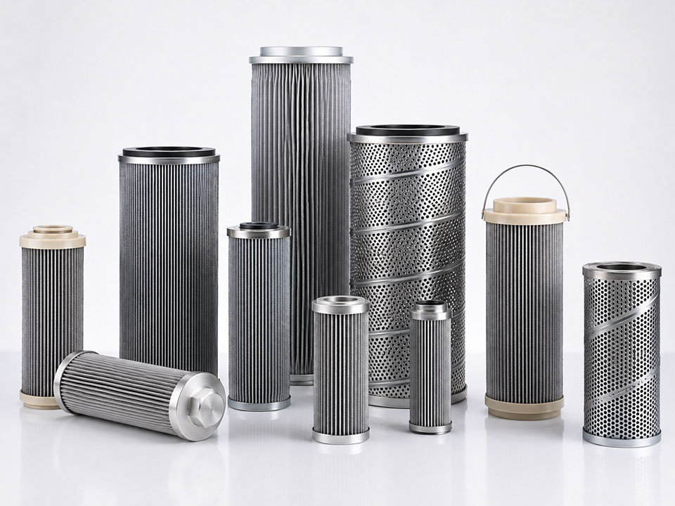
Indiquez à notre équipe d'assistance commerciale le type de produit, la finesse de filtration (en microns), la taille, l'application, le matériau filtrant, la température de service, la pression et la quantité estimée. Nous vous aiderons à trouver la cartouche filtrante adaptée, qu'elle soit en plastique fritté, en métal fritté ou de type sédimentaire.
That answer is technically correct, yet almost useless, because the real behavior of a sintered filter depends on how those pores connect, where they tighten, how sharply the channels turn, what the contaminant feels like, and how aggressively the operator pushes the fluid through.
Simple? Not really.
A sintered filter works by forcing liquid or gas through a rigid porous body made from bonded metal or polymer particles. Fluid moves through interconnected voids. Contaminants don’t. Or, more accurately, some don’t—because particles may be blocked at the face, wedged inside a constriction, knocked into a pore wall, caught in an existing dirt cake, or carried straight through.
That last possibility tends to disappear from sales brochures.
It shouldn’t.
What Is a Sintered Filter Actually Made From?
Start with powder.
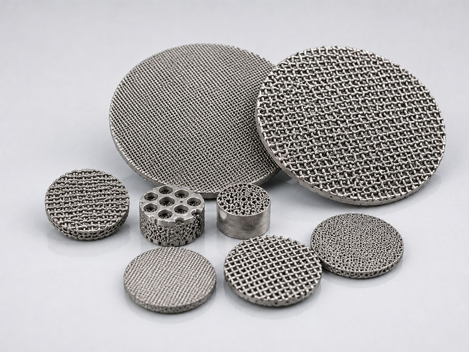
Metal powder, polymer powder, metal fibers, woven mesh layers—sometimes a stacked combination. The raw material is shaped and heated below its full melting point until adjoining particles bond at their contact points. Enough open space is deliberately left behind to create a stable network of pores.
Those empty spaces are the working media.
Change the powder distribution and the pore structure changes. Increase compaction and permeability can fall. Alter the heating cycle and you may affect bonding strength, dimensional shrinkage, pore shape, and repeatability between batches.
According to Mott Corporation, powder size, pressing, and the sintering operation collectively influence pore distribution, strength, and permeability in porous metal elements. (Mott Corporation)
That’s the unglamorous truth: filtration performance begins in powder preparation and furnace control, long before the cartridge reaches a housing.
Common metal options include:
304 stainless steel
316L stainless steel
Bronze
Titanium
Nickel-based alloys
Corrosion-resistant specialty alloys
Plastic media may use:
Polyethylene, including PE and UHMWPE
Polypropylene, or PP
Polytetrafluoroethylene, or PTFE
Nylon, also called PA
Application-specific engineering polymers
The underlying porous filter filtration mechanism is similar in both categories. Their allowable temperature, pressure, chemical exposure, sterilization method, and mechanical abuse are not.
The Sintered Filter Working Principle—Without the Sales Talk
1. Differential Pressure Makes the Fluid Move
Nothing flows merely because pores exist.
The filter needs a pressure difference: higher pressure upstream, lower pressure downstream. That difference—normally written as ΔP—drives liquid or gas into the porous wall and out the clean side.
For relatively slow, laminar flow through porous media, Darcy’s law gives a useful first approximation:
ΔP ≈ μLv/k
Où :
ΔP = differential pressure
μ = dynamic viscosity
L = media thickness
v = superficial flow velocity
k = permeability
The equation isn’t decorative. It explains several shop-floor problems almost immediately.
Higher viscosity? Expect more resistance.
Thicker wall? More resistance.
Lower permeability? Again—more resistance.
Push twice the flow through an undersized cartridge and then blame the filter for “high pressure drop”? I frankly believe that’s one of the industry’s laziest diagnostic habits.
The University of Illinois explains porous flow resistance using pressure gradient, fluid viscosity, path length, area, and permeability in its discussion of Darcy flow through porous material. The simple relationship becomes less reliable when gas compressibility, turbulence, slip flow, or high velocity enters the picture, but it remains a sound engineering starting point.
2. The Fluid Enters a Crooked Pore Network
Forget the neat diagram of identical, straight holes.
Real sintered media looks more like a three-dimensional alleyway built between fused grains. One passage narrows. Another widens. Two channels merge, then split again. Dead-end pockets appear. Surface texture changes from point to point.
The fluid takes the available route.
That winding route is described as tortuosity. Higher tortuosity can create more particle-to-wall contact and a longer effective travel distance, but it also adds resistance and gives contaminants more places to become permanently lodged.
Good for capture.
Bad for cleaning.
And this is why “10 μm pore size” doesn’t tell me enough. Is that a mean flow pore? A maximum opening? A nominal retention number? A bubble-point correlation? A microscopy estimate? An efficiency rating measured with a stated challenge dust?
Same number. Different meaning.
3. Contaminants Are Caught by Several Mechanisms
Size exclusion gets all the attention because it’s easy to draw.
A particle is larger than the hole. It stops.
Done.
But a functioning sintered filter is rarely that tidy. The active capture mechanism shifts with particle diameter, shape, density, velocity, surface condition, viscosity, concentration, electrostatic charge, moisture, and the amount of dirt already sitting in the media.
Size Exclusion
Particles too large to enter the available pore opening remain on or close to the upstream surface.
This is classic screening. The U.S. EPA describes sediment and microporous filtration as physically capturing suspended solids larger than the rated pore size at the media surface. (US EPA)
Yet even here, “larger” isn’t always straightforward.
A rigid spherical particle behaves predictably. A flexible gel fragment doesn’t. A needle-shaped contaminant may rotate and enter lengthwise. An agglomerate can break under shear. Soft biological material may compress through an opening that appears smaller on paper.
Catalog logic breaks quickly.
Direct Interception
A particle follows the moving fluid but passes close enough to a pore wall to touch it.
Once contact occurs, adhesion, surface roughness, moisture, oil, or mechanical wedging may keep it there. The particle doesn’t have to be larger than the pore entrance. It only has to collide with the internal structure and fail to detach.
Inertial Impaction
The fluid turns. A heavier particle doesn’t turn fast enough.
Its momentum carries it out of the streamline and into a pore wall. This effect generally becomes more noticeable with denser particles, higher velocity, and sharper changes in flow direction.
Fast flow isn’t free.
It can increase capture by impaction, but it can also raise ΔP, drive fines deeper into the media, compact the cake, or push weakly retained material downstream.
Brownian Diffusion
Very small aerosol particles don’t travel in perfectly smooth lines. Molecular collisions make them wander.
That random movement increases the chance of contacting an internal surface, which is why gas-filtration behavior can’t always be predicted by comparing one pore diameter against one particle diameter.
The smallest particles can behave oddly.
Bridging
One particle enters. Another catches beside it. A third spans the remaining gap.
Soon, the pore entrance is bridged by material that might individually have passed through. Once that bridge forms, larger quantities of solids build on top of it.
A temporary defect becomes an active filter layer.
Adhesion and Mechanical Lodging
Sticky resin, oily soot, crystalline salt, catalyst fines, metal oxide, soft biological solids, and dry mineral dust do not load media in the same manner.
Some particles cling chemically. Others lock into surface asperities. A few become packed into pore throats like grit under a valve seat.
And some never come out.
That’s the part usually discovered after the third cleaning cycle, when the cartridge looks spotless but clean-flow resistance has quietly doubled.
Surface Filtration and Depth Filtration Aren’t Opposites
People like clean categories. Filters don’t care.
A sintered element may begin with depth capture, shift toward surface loading, and later operate mainly through a contaminant cake. The mechanism changes while the cartridge remains in the same housing.
Surface Filtration
Surface filtration keeps most solids at or near the upstream face. As loading continues, retained particles build a cake.
That cake becomes part of the filtration system.
This operating mode is often preferred when:
Solids loading is relatively high
The contaminant forms a permeable cake
Product recovery matters
Blowback or backwashing is planned
Deep pore plugging must be limited
The process needs repeatable regeneration cycles
But cake filtration has an awkward personality. A loose cake can improve retention without causing a huge pressure penalty. A compressible cake can collapse, seal over, and send differential pressure climbing almost vertically.
Same filter. Different sludge.
Depth Filtration
Depth filtration allows particles to enter the porous body before they’re intercepted, impacted, bridged, adhered, or mechanically trapped.
There’s usually more internal holding volume. That sounds attractive—and sometimes it is.
Yet deeply lodged contamination is stubborn. Reverse flow may peel off the surface layer while leaving fine material packed inside narrow pore throats. The element flows again, but never quite like new.
Mott’s porous-metal guidance notes that a removable surface cake can permit pressure recovery after cleaning, whereas progressive internal loading may prevent the original clean pressure drop from being fully restored. (Mott Corporation)
Here’s the ugly truth: “reusable” describes construction potential, not guaranteed cleaning success.
What Happens as a Sintered Filter Loads?
The cartridge you install and the cartridge you remove are hydraulically different objects.
The Clean-Media Stage
At startup, the manufactured porous structure controls resistance. This is the clean baseline—the number maintenance teams should record and then promptly lose in a spreadsheet nobody can find six months later.
Record it properly:
Fluid
Température
Inlet pressure
Outlet pressure
Débit
Cartridge quantity
Housing arrangement
Fluid viscosity, where relevant
A ΔP reading without operating conditions is nearly meaningless.
Ten kilopascals across water at 20°C isn’t comparable with ten kilopascals across cold hydraulic oil. Gas readings are even trickier because density and compressibility change with pressure.
Early Pore Loading
Fine contaminants begin entering the structure.
Some stick. Some bridge. Others travel deeper before stopping. Available flow paths narrow, so permeability falls. At the same time, retention may appear to improve because the partially loaded media now has smaller effective passages.
That can fool operators.
The filter seems to be “working better” right before it starts choking the process.
Cake Development
Enough material accumulates for the upstream deposit to behave as a separate porous layer.
Now the cake may capture particles that the clean filter wouldn’t reliably retain. Product clarity improves. Pressure drop rises. The deposition pattern becomes more important than the original pore rating.
This is often the desired operating state in catalyst recovery, hot-gas filtration, and high-solids liquid service—provided the cake remains permeable and can later be removed.
Terminal Loading
Eventually, the run ends.
Not necessarily because the pores are completely blocked. A cycle may stop because:
Differential pressure reaches the approved limit.
Flow drops below the production target.
Product cleanliness becomes unstable.
Cake space inside the housing is exhausted.
The pump or compressor reaches its operating limit.
The process can no longer tolerate the energy loss.
Operators sometimes keep pushing.
That’s rarely clever. Excessive ΔP can compact the deposit, drive fines deeper, deform unsupported parts, damage seals, collapse weaker media, or make the next cleaning cycle far less effective.
Why Differential Pressure Beats a Maintenance Calendar
“Clean every Friday” is easy to schedule.
It’s also often poor process control.
A filter handling a clean batch may remain healthy for weeks. The same element can blind in forty minutes after an upstream separator fails, a tank heel is disturbed, or an operator sends an off-spec slurry into the line.
Differential pressure reveals the change while it’s happening.
Le EPA’s March 2024 WaterSense guidance recommends using pressure sensors to determine when resistance is high enough to justify backwashing, rather than cleaning filtration equipment more frequently than necessary. The same document identifies approximate removal scales of 0.1 μm for microfiltration et 0.01 μm for ultrafiltration, though those classifications shouldn’t be mistaken for universal sintered-filter ratings. (US EPA)
Pressure-based cleaning avoids two expensive mistakes:
Cleaning too early and wasting water, chemicals, compressed gas, labor, or production time
Cleaning too late and compacting contamination until recovery becomes poor
Still, ΔP is an indicator—not a diagnosis.
A rising pressure drop says resistance increased. It doesn’t tell you whether the cause is normal cake loading, cold fluid, polymer solidification, biological growth, sticky carryover, a blocked outlet valve, or a damaged pressure transmitter.
Someone still has to think.
Sintered Filter Pore Size Is Not the Same as Filtration Rating
I’d put this warning in red on every industrial filter quotation.
Pore size describes the porous structure. Filtration rating describes particle-retention performance under defined test conditions.
Related? Yes.
Interchangeable? No.
A filter with a characteristic pore size of 20 μm may catch many smaller particles through interception, tortuosity, bridging, or cake formation. That doesn’t magically make it an absolute 5 μm filter.
Likewise, a contaminant larger than the published pore value may sometimes pass if it is flexible, elongated, compressible, or fragmented under pressure.
Ask the supplier:
Which pore-size method was used?
Is the stated value mean, maximum, nominal, or absolute?
What retention efficiency was achieved?
Which test particles were used?
Were they spherical, irregular, rigid, or deformable?
What fluid carried them?
At what velocity?
At what pressure?
Was the media clean or preloaded?
Was the result measured in liquid or gas?
Without those details, a micron number is mostly decoration.
Mott’s technical overview, for example, distinguishes media grade, mean flow pore, and filtration rating rather than treating them as a single value. (Mott Corporation)
What Actually Controls Sintered Filter Performance?
Design or operating variable
What changes inside the filter
Likely system effect
Common purchasing mistake
Smaller pore openings
Fewer large passages remain available
Higher retention, usually higher clean ΔP
Selecting the smallest rating available
Higher porosity
More void volume is available for flow
Higher permeability and potential dirt capacity
Assuming porosity alone determines retention
Greater tortuosity
Fluid follows longer, more complex paths
More internal contact, potentially harder cleaning
Ignoring deep contamination
Thicker media wall
Flow travels through more porous material
Higher resistance and possible depth capacity
Copying dimensions without flow testing
Higher fluid viscosity
More force is needed to maintain flow
Higher differential pressure
Testing with water when service fluid is oil
Higher face velocity
More fluid crosses each unit of area
Higher ΔP and possible particle penetration
Reducing filter area to save housing cost
Broad particle distribution
Fine particles fill gaps between coarse solids
Faster pore blockage or denser cake
Specifying only the largest particle
Compressible contaminants
Cake compacts as pressure rises
Rapid and nonlinear ΔP increase
Expecting easy backwashing
Sticky or oily solids
Particles adhere strongly to internal surfaces
Poor regeneration and residual resistance
Assuming every rigid filter is reusable
Excessive cleaning pressure
Cake removal becomes aggressive
Media damage or contaminant breakthrough
Treating stronger cleaning as better cleaning
The table matters because filters fail as systems, not as isolated materials.
A cartridge can have suitable metallurgy and still be too small. The area may be adequate, yet the cake can be compressible. The micron rating may be right, but the seal elastomer swells. Or the filter cleans beautifully with solvent—except the process doesn’t permit solvent residues.
Every specification has a loose thread.
Pull it.
Three Real Cases That Show What Porous Filters Really Do
Case 1: NASA, Lunar Regolith, and the Trouble With Fines
This isn’t a conventional factory filter application. That’s exactly why it’s useful.
NASA’s 2023 Mini-ROXY white paper examined a porous metal cathode cup used in a molten-salt electrolysis system intended to process lunar regolith. The porous structure had to permit electrolyte exchange and oxygen-ion movement while retaining solid material.
Then the fines showed up.
The paper identified potential loss of processed regolith particles smaller than 10 μm through the porous cathode cup. Those escaped particles could reduce material yield, enter the salt electrolyte, accumulate over repeated cycles, and change properties such as conductivity or optical basicity.
The proposed response wasn’t “buy a finer filter.”
Instead, the team considered upstream particle-size sorting, cathode pore size, pore structure, tortuosity, and total porosity together. The paper describes potential sorting thresholds in the 10–50 μm range, depending on the cathode design.
And the temperature? Hardly forgiving.
The salt-separation stage involved centrifugation above 700°C, using a porous, temperature-resistant, corrosion-resistant structure that would pass molten salt while holding back processed regolith. Ground testing involved centrifuge equipment designed for more than 800°C and up to 1,000 RPM.
Read the NASA Mini-ROXY white paper, and the lesson becomes hard to miss: feed preparation and porous-media design are one problem—not two separate purchasing decisions.
Case 2: Soot Loading on a Sintered Metal Filter
Soot is nasty filter feed.
It’s fine, cohesive, mobile, and capable of building a layer whose behavior changes dramatically during heating. A 2023 study in Emission Control Science and Technology tracked soot deposition and regeneration inside a wall-flow channel containing sintered metal media.
The generated soot had a modal agglomerate size near 90 nm, with primary particles around 20–40 nm. The test used a soot mass flow of 40 mg/h. (Springer)
As loading increased, the measured particle layer thickened:
6 mg soot: about 68 μm
12 mg soot: about 135 μm
18 mg soot: about 200 μm
Yet the layer didn’t behave like a neat, stationary blanket. During regeneration it oxidized, cracked, shrank, detached, and resuspended.
Temperature changed the outcome sharply.
At a final regeneration temperature of 480°C, soot remained after two hours. At 600°C, the particles were fully oxidized after 51 minutes, cutting the reported regeneration time by 55%. (Springer)
Le full Springer study is worth reading because it shows something a static product datasheet can’t: the cake is a changing mechanical structure, not just “dirt on a filter.”
But don’t copy the 600°C number blindly.
Different soot chemistry, oxygen concentration, alloy, media thickness, flow velocity, catalyst content, and thermal ramp could produce a different result—or a damaged cartridge.
Numbers need context.
Case 3: EPA Guidance on Pressure-Based Backwashing
The EPA example is less dramatic. It may be more useful.
In its 2024 water-purification guidance, the agency describes surface capture of suspended contaminants and advises facilities to use pressure sensors when deciding whether backwashing is needed. (US EPA)
Why does that matter?
Because many plants still clean filters based on habit, shift changes, calendar intervals, or a vague sense that “it has probably been long enough.”
Pressure-based control responds to actual resistance.
That reduces premature washing, but it also helps prevent late cleaning—when the cake has already compacted, the flow has collapsed, and the operator responds by increasing pump pressure.
I’ll be blunt: waiting until production notices the filter is not a maintenance strategy.
How Does a Sintered Metal Filter Work Differently?
Mechanically, the filtration concept is the same. Fluid still moves through connected pores. Particles are still captured by exclusion, interception, impaction, bridging, adhesion, and cake formation.
The difference is what the structure can survive.
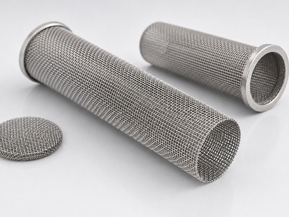
A cartouche filtrante en métal fritté may be considered when the process involves high temperature, steam exposure, high differential pressure, abrasive solids, thermal regeneration, repeated blowback, vacuum conditions, or aggressive chemicals compatible with the selected alloy. (lvyn)
Metal media may offer:
High structural rigidity
Stable geometry under pressure
Welded construction
Resistance to media migration
Compatibility with aggressive cleaning
Potential for repeated regeneration
Better tolerance of thermal cycling
Long operating life in suitable service
Sounds unbeatable.
Ce n'est pas le cas.
Very fine sintered metal media can impose substantial clean ΔP. Stainless steel can pit or suffer crevice corrosion. High temperature can introduce oxidation, creep, or thermal-fatigue issues. Welds and end fittings may fail before the porous wall does. A brittle cake may detach and overload downstream equipment after blowback.
And 316L isn’t a magic spell.
The alloy, weld filler, passivation condition, chloride concentration, temperature, pH, and stagnant zones all matter.
How Does a Sintered Plastic Filter Work Differently?
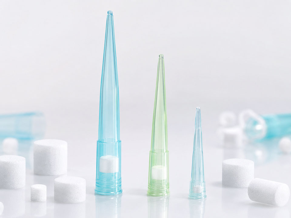
Sintered plastic uses bonded polymer particles to form the same broad type of rigid, tortuous pore network.
The operating envelope changes.
Plastic media is commonly selected for:
Lower component weight
Resistance to selected chemicals
Economical custom shapes
Integrated polymer connections
Venting and gas diffusion
Pneumatic silencing
Water and low-temperature liquid filtration
Medical and laboratory components
Compact OEM assemblies
Hydrophobic or hydrophilic behavior, depending on material and treatment
But “plastic” is far too broad to be useful.
PE, PP, PTFE, and nylon have different chemical resistance, wettability, dimensional behavior, sterilization tolerance, temperature range, and mechanical strength.
A PTFE vent filter and a PE depth filter may both be sintered polymer products. Operationally, they’re distant relatives.
Material-first selection feels technical. Sometimes it’s backwards.
Can a Sintered Filter Catch Particles Smaller Than Its Pores?
Yes.
But don’t turn that answer into a marketing claim without test data.
Sub-pore capture can occur because:
The quoted pore value is an average rather than the smallest constriction
Internal channels tighten after the entrance
Particles intercept pore walls
Inertia pushes dense particles out of streamlines
Brownian motion increases contact among tiny aerosols
Irregular particles become mechanically wedged
Several particles bridge an opening
Existing deposits capture incoming fines
A cake develops with finer effective passages
So a 20 μm structure might capture a portion of 10 μm contaminants. It may even capture many of them under a specific test.
That doesn’t prove a 10 μm absolute rating.
No defined efficiency, no defensible claim.
Why Filter Area Is Often More Important Than Buyers Expect
A cheap filter housing frequently becomes an expensive operating decision.
Suppose one cartridge provides half the media area actually needed. Face velocity rises. Clean ΔP increases. Particles may be driven deeper into the wall. Cake loading becomes less uniform. Run time shortens. Cleaning frequency rises.
Then the plant buys more cartridges.
Repeatedly.
Increasing media area can lower superficial velocity, reduce clean resistance, create more cake capacity, and extend the time between regeneration cycles. The larger initial housing may cost more, but total operating cost can fall.
Here’s the ugly truth: procurement savings and process savings aren’t always friends.
Why Viscosity Can Destroy a Filter Calculation
Water test data is convenient.
Your actual fluid may be cold oil.
Viscosity directly influences the pressure required to maintain flow. A cartridge showing an acceptable clean ΔP with room-temperature water may become painfully restrictive with viscous resin, syrup, lubricant, concentrated chemical solution, or low-temperature fuel.
And viscosity changes with temperature.
A system can run perfectly at 60°C, shut down overnight, then alarm on differential pressure during a cold restart—even though no additional contamination entered the filter.
The filter didn’t suddenly clog.
The fluid thickened.
This is why a serious flow test needs either the real process fluid or a carefully chosen substitute with comparable viscosity, density, wettability, and surface tension.
“Tested with water” shouldn’t end the discussion. It should start another one.
How Are Sintered Filters Cleaned?
Cleaning should attack the contamination mechanism without attacking the filter.
That sounds obvious. Practice says otherwise.
Reverse Liquid Flow
Clean liquid moves through the element opposite the normal filtration direction, lifting the cake from the upstream surface.
This works best when contamination remains shallow, doesn’t adhere strongly, and hasn’t compacted into the pore structure.
A mild backwash may do nothing.
An excessive one may damage the assembly, dislodge support components, or redeposit contamination elsewhere in the housing.
Gas Blowback
Compressed gas is pulsed backward through the media to fracture and dislodge the cake.
Pulse pressure matters. So do receiver volume, valve opening speed, nozzle geometry, gas temperature, element spacing, and the pressure remaining on the dirty side.
A pressure number alone doesn’t describe cleaning energy.
Ultrasonic Cleaning
Ultrasonic cavitation can release material from exposed surfaces and internal passages. It’s often useful for small, rigid components.
But ultrasonic cleaning isn’t sorcery.
It may fail against baked-on polymer, strongly adhered oxide, hardened resin, deep abrasive packing, or contaminants shielded inside blind regions. It can also damage fragile joints or unsupported features if the procedure is too aggressive.
Chemical Cleaning
Acid, alkali, solvent, detergent, oxidizer, or chelating chemistry may dissolve or loosen contamination.
Compatibility must cover the whole assembly:
Porous media
Welds
Brazed joints
Adhesives
End caps
Seals
Surface treatments
Downstream purity requirements
A stainless body may tolerate the cleaning fluid while an elastomer seal does not.
That still counts as failure.
Thermal Regeneration
Suitable metal filters can sometimes be heated to oxidize organic contamination.
Know the deposit first.
Unknown residues may release hazardous gases, leave corrosive ash, ignite unexpectedly, react with the alloy, sinter into a harder deposit, or create thermal gradients that distort the cartridge.
“Burn it clean” is not an engineering procedure.
Combination Cleaning
Real regeneration processes often use several stages:
Blowback or reverse flushing
Chemical soaking
Ultrasonic agitation
High-purity rinsing
Controlled drying
Flow testing
Integrity testing
Clean packaging
That final testing step separates actual regeneration from cosmetic cleaning.
A shiny filter can still be blocked.
How Do You Know Whether Cleaning Worked?
Compare the element with a defined baseline.
Useful checks may include:
Flow at a controlled differential pressure
Differential pressure at a controlled flow
Bubble-point or pore-integrity testing
Visual inspection under magnification
Dimensional inspection
Particle-shedding assessment
Contaminant residue analysis
Filtration-efficiency testing
Weld and seal inspection
Clean pressure recovery is especially revealing.
Suppose a new cartridge produces 20 kPa ΔP at a specified flow. After service and cleaning, it produces 26 kPa. Later it returns at 34 kPa. Then 45 kPa.
It’s still flowing.
But internal plugging is accumulating.
Whether it remains usable depends on the process margin, retention requirement, cleaning economics, and risk of contaminant release. Eventually, the element becomes a permanent pressure-loss device with a filter attached.
When Should a Sintered Filter Be Replaced?
Not when it looks old.
Replace it when validated performance can’t be restored—or when continued use creates unacceptable process risk.
Typical warning signs include:
Cleaned ΔP remains above the approved recovery limit
Required flow can’t be achieved
Filtration efficiency has deteriorated
Bubble-point or integrity testing fails
The media is cracked, distorted, eroded, or corroded
Welds or fittings show damage
Cleaning cycles become progressively shorter
Contamination can’t be verified as removed
Product purity requirements have increased
The cost of validation exceeds replacement cost
A filter may remain physically intact and still be unfit for service.
That distinction becomes especially important in medical devices, pharmaceuticals, food and beverage production, catalyst recovery, high-purity gas, critical cooling systems, and any process where downstream contamination carries a large financial or safety penalty.
How to Specify a Sintered Filter Without Guessing
Don’t begin with “We need a 10-micron cartridge.”
Begin with the feed.
Define the Fluid
State:
Liquid or gas
Chemical composition
Concentration
Viscosity
Density
Normal temperature
Minimum and maximum temperature
Working pressure
Potential chemical upsets
Define the Contaminant
Include:
Matériau
Particle-size distribution
Forme
Concentration
Density
Hardness
Whether it is abrasive
Whether it is sticky
Whether it is compressible
Whether it agglomerates
Whether it is valuable and must be recovered
One D50 number isn’t enough.
Fine tails usually cause the trouble.
Define the Required Result
Specify:
Target retained particle size
Required efficiency
Maximum allowable downstream count
Product-clarity requirement
Permitted startup shedding
Whether breakthrough is tolerable
Applicable validation method
Define the Hydraulic Limits
Provide:
Normal flow
Peak flow
Minimum flow
Clean ΔP target
ΔP au niveau du terminal
Pump or compressor capability
Available filtration area
Allowed cycle length
Define the Cleaning Method
State whether the element will be:
Disposable
Backwashed
Gas-pulsed
Ultrasonically cleaned
Chemically cleaned
Steam sterilized
Thermally regenerated
Cleaned off-site
The proposed cleaning method may determine the material before the filtration rating does.
Define the Physical Interface
Include drawings where possible:
Outside diameter
Inside diameter
Longueur
Wall thickness
Thread
Flange
Welded connection
Gasket type
Sealing face
Installation orientation
Housing clearance
Required tolerances
For non-standard geometry, replacement-part development, custom connections, or drawing-based production, an OEM/ODM sintered filter program should start with process data—not a blurry photograph beside a ruler. (lvyn)
And before approving repeat production, buyers should examine the supplier’s filtration factory and testing capability, including material control, furnace management, dimensional inspection, flow testing, pressure-drop verification, and batch traceability. (lvyn)
Factory size photographs are nice.
Test methods are better.
Foire aux questions
How do sintered filters work?
A sintered filter works by forcing a liquid or gas through a rigid network of bonded particles and interconnected pores, where oversized contaminants are screened at the face and smaller particles are caught by interception, impaction, adhesion, bridging, or depth capture inside the media.
As loading continues, captured material narrows the open passages and may develop into a surface cake. Differential pressure rises until the cartridge is backwashed, blown clean, chemically regenerated, thermally treated, or replaced.
What is the difference between surface and depth filtration?
Surface filtration holds most contamination on the upstream face and gradually forms a removable cake, whereas depth filtration allows particles to enter the porous wall and become trapped within tortuous passages through interception, adhesion, bridging, impaction, or mechanical lodging.
In actual service, both mechanisms may occur during one cycle. Surface loading is usually easier to reverse. Depth loading may provide additional holding capacity, but fine material embedded inside pore throats is often harder to remove.
Does sintered filter pore size equal its micron rating?
A sintered filter’s pore size describes a measured or calculated feature of its porous structure, while its micron filtration rating describes particle-retention performance under stated test conditions; the two values are related, but they aren’t automatically identical or interchangeable.
Buyers should confirm whether the published value is nominal, absolute, maximum pore, or mean flow pore—and ask for the test fluid, particle type, flow velocity, differential pressure, and measured efficiency.
Why does pressure drop increase across a sintered filter?
Pressure drop rises because deposited particles reduce open flow area, narrow internal pore passages, and build an additional cake layer that resists flow; increasing viscosity, face velocity, media thickness, contaminant concentration, or cake compressibility can make that rise substantially faster.
A gradual increase often reflects normal loading. A sudden jump may point to a process upset, cold fluid, sticky contamination, damaged pretreatment equipment, rapid cake compaction, or a restriction elsewhere in the piping.
Can sintered filters be cleaned and reused?
Many sintered filters can be cleaned and reused because their bonded porous structure may tolerate reverse flow, gas blowback, ultrasonic treatment, compatible chemicals, steam, or controlled heating, but actual reusability depends on the media material, contaminant behavior, assembly design, and cleaning procedure.
After cleaning, the element should be checked against an approved flow, differential-pressure, integrity, dimensional, or retention baseline. Looking clean isn’t the same as performing correctly.
Is a sintered metal filter better than a sintered plastic filter?
A sintered metal filter is generally better suited to elevated temperature, high differential pressure, thermal regeneration, abrasive solids, and severe mechanical cleaning, while a sintered plastic filter may offer lower weight, economical custom geometry, selected chemical resistance, and easier integration into compact OEM assemblies.
Neither is automatically superior. Fluid chemistry, operating temperature, pressure, required retention, cleaning method, sterilization conditions, geometry, regulatory documentation, production volume, and total life-cycle cost should decide.
Stop Buying Filters by Micron Rating Alone
A sintered filter isn’t a porous tube plus a nice round number.
It’s a pressure-driven system involving media geometry, fluid rheology, contaminant behavior, active area, cake structure, cleaning energy, mechanical limits, and the uncomfortable question nobody wants to ask: what happens when the process stops behaving normally?
Send the real data:
Process fluid
Contaminant type
Full particle-size distribution
Required retention efficiency
Normal and peak flow
Viscosity
Température
Working pressure
Pression différentielle maximale
Cartridge dimensions
Méthode de nettoyage
Annual quantity
The engineering team can then review the requirement through the custom OEM/ODM filter development service and compare sintered plastic or metal structures against the operating conditions.