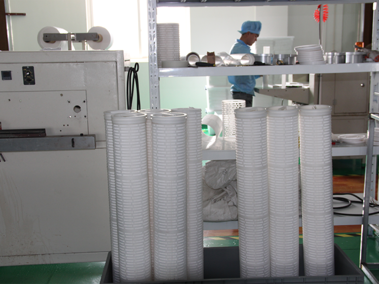
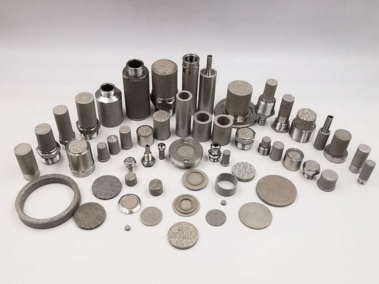
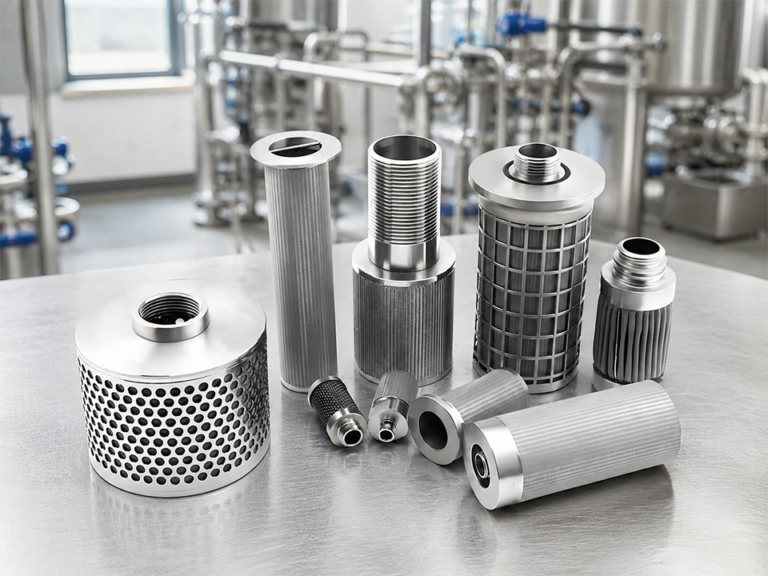
Before you leave, we invite you to talk directly with our managing team to ensure you receive the most accurate technical guidance, pricing support, and customization options for your project. Our experts can quickly evaluate your requirements, recommend suitable sintered plastic filter solutions, and help you reduce sourcing risks while improving efficiency, consistency, and long-term supply stability for your industrial applications.
Need Help Selecting the Right Filter Cartridge?
Our Sales Team
Tell our sales support team your product type, micron rating, size, application, filtered medium, working temperature, pressure, and estimated quantity. We will help you match the right sintered plastic, sintered metal, or sediment filter cartridge.
How to Select Filter Geometry: Cartridge, Disc, Tube or Plate
A filter shape can wreck a good skid.
Not because the media is bad, not because the micron rating is wrong, and not because the buyer picked the wrong alloy—but because somebody chose a geometry that looked neat in CAD and then forgot about sealing compression, housing clearance, dirty-side access, drain position, manifold flow distribution, and the miserable technician who has to pull the thing out at 2 a.m. Ever seen that fight?
I have.
Filter geometry is not styling. It is hydraulic behavior, sealing logic, service access, pressure-drop control, and installation risk packed into one shape. Cartridge, disc, tube, and plate designs all work. They also fail differently. And the wrong geometry can turn a simple filtration job into a piping modification, a leak path, a bypass problem, or a maintenance curse.
Tiny shape. Big bill.
Here’s the ugly truth: engineers often select media first and geometry second. I think that’s backwards in brownfield systems. If the housing, nozzle orientation, skid footprint, cover lift, clamp style, drain point, or manifold bolt pattern is fixed, geometry may be the first constraint—not the last.
For product and design context, connect this article with sintered metal filter cartridges, sintered plastic filter cartridges, custom filter cartridge manufacturing, sintered filter pressure drop, and filter certification requirements. A filter element does not live alone. It lives inside a housing, inside piping, inside a plant that probably has less room than the drawing pretends.
Start with the housing, not the filter media
But don’t start with “cartridge or disc?”
Start with the box around it.
What housing do you already have? Vertical or horizontal? Top-open or side-open? Swing bolt or clamp? Is there enough lift clearance? Can an operator pull a 40-inch element without hitting a pipe rack? Is there a drain? Is there a vent? Can the dirty chamber be cleaned? Can the clean side be protected during service? Can a gasket be inspected without a mirror and a curse word?
That’s the real beginning.
Parker’s filtration handbook notes that filter housings are generally designed for circuit locations such as suction, pressure or return lines, and that location affects housing selection and filter behavior: Parker hydraulic filtration handbook. Different market, same engineering lesson: the element geometry has to fit the system role, not just the catalog page.
In new skid design, geometry is freedom.
In retrofit work, geometry is negotiation.
Brownfield systems do not care about your favorite filter shape. They care about nozzle spacing, bolt circles, old pipe stress, access platforms, and how much downtime the plant manager will tolerate.
Cartridge geometry: popular because it solves boring problems
Cartridge geometry is the default for a reason.
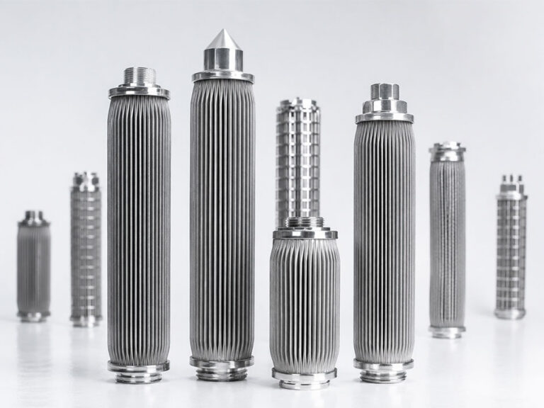
Long cylinder. Easy to house. Easy to scale by adding length, diameter, pleats, or multiple elements. Straightforward sealing with O-rings, gaskets, end caps, threaded adapters, bayonet ends, DOE/SOE styles, or custom seats. It works in water, gas, oil, chemical, food, pharma, hydraulic, and process systems.
Usually.
A filter cartridge geometry gives designers a clean way to increase surface area without inventing a new housing every time. Use a longer cartridge. Use multiple cartridges. Use pleats. Use larger OD. Use high-flow format. Done—at least on paper.
But cartridges need axial clearance. They need a reliable seat. They can suffer from bypass if the end seal is sloppy. Long cartridges can bend or vibrate under flow. Heavy metal cartridges can be annoying to remove. In horizontal housings, dirt can settle badly. In vertical housings, top access may be impossible if the skid is under a mezzanine.
I’ve seen a perfect cartridge spec fail because nobody checked ceiling clearance.
Beautiful drawing.
Useless installation.
Use cartridge geometry when you need modular replacement, standard housings, high surface area, easy spare parts, and predictable service workflow. Be careful when access space is tight, when the housing cannot tolerate axial removal, or when seal alignment is hard to control.
Disc filter design: compact, sharp, and unforgiving
Disc filters look simple.
Flat circle. Easy, right?
Not exactly.
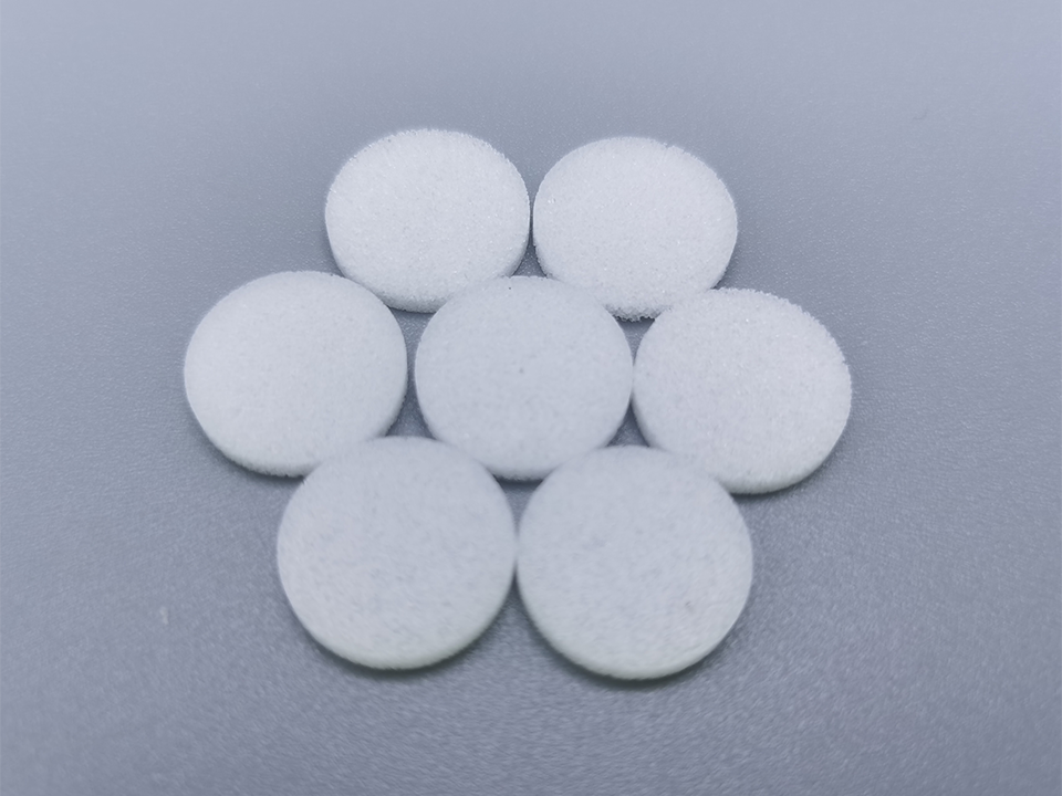
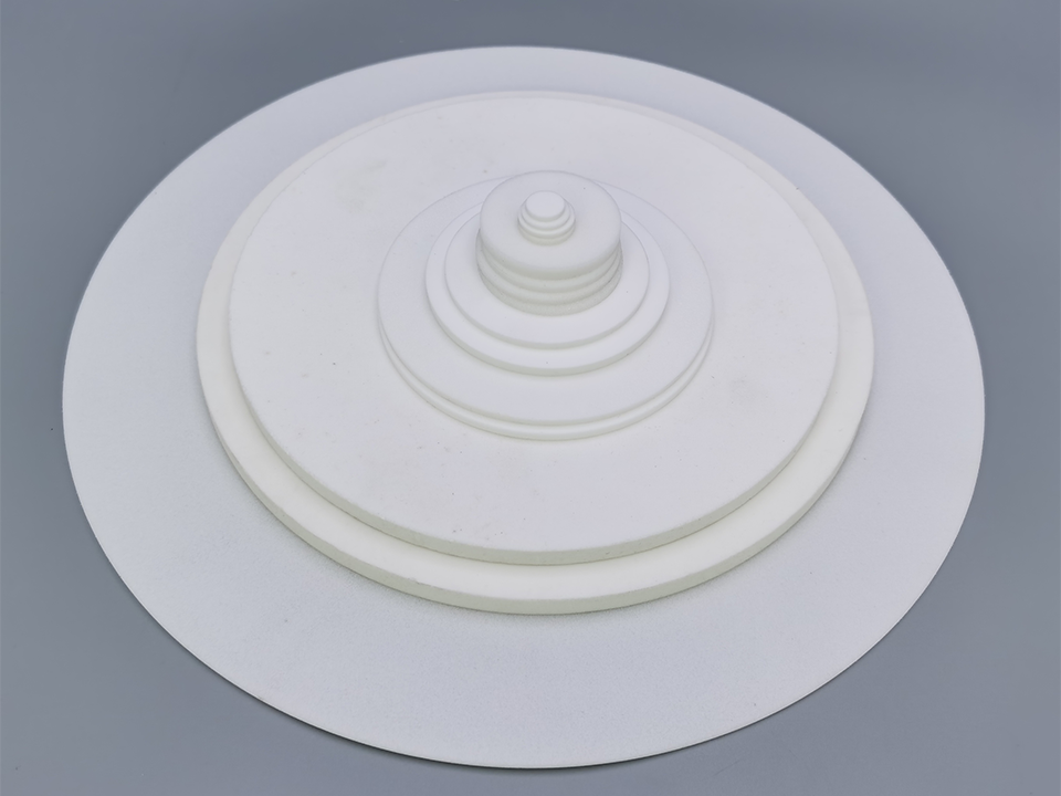
A disc filter design can be excellent when the system needs a compact element, low profile, controlled flow path, support between plates, or filtration inside a small assembly. Sintered discs, mesh discs, porous plastic discs, and perforated support-disc designs are common in valves, regulators, diffusers, vents, analytical devices, small manifolds, and OEM components.
The advantage is compactness.
The weakness is sealing.
A disc usually depends on face sealing, compression control, gasket condition, flatness, surface finish, and support. If the disc is not seated evenly, the flow bypasses the media and laughs at your micron rating. If differential pressure is high and support is weak, the disc can deform. If the housing has poor alignment, one side loads harder than the other.
From my experience, disc filters are great in controlled assemblies and risky in sloppy housings.
Use disc geometry when you need short axial length, compact packaging, and simple replacement in a controlled seat. Avoid it when sealing surfaces are rough, compression is uncontrolled, or the operator may reinstall it backward, tilted, or dirty.
Yes, they will.
Tube filter element: good flow path, awkward handling
Tube geometry is honest.
Fluid goes through a porous cylinder wall. Inside-out or outside-in. Simple visual logic. Sintered metal tubes, porous plastic tubes, ceramic tubes, wedge wire tubes, and mesh tubes can provide strong support, good cylindrical surface area, cleanable media, and useful geometry for gas sparging, venting, catalyst recovery, high-temperature filtration, or process-fluid service.
A tube filter element can be open-ended, closed-ended, welded to a header, threaded, flanged, or installed as a bundle. Bundles can create a lot of filtration area in a pressure vessel. Good design.
But tubes demand manifold discipline.
If flow distribution is poor, some tubes load early while others coast. If the header welds are weak, fatigue appears. If the tube is too long and unsupported, vibration can become a problem. If the clean side and dirty side are not clearly isolated, bypass hides inside the assembly.
The EPA membrane filtration manual discusses membrane modules and system configuration as part of filtration application and design, including how module integrity and operation affect performance: EPA membrane filtration guidance manual. Sintered tubes are not membrane modules, but the lesson holds: geometry and module layout decide how flow actually reaches the media.
I like tube elements for cleanable, high-temperature, high-pressure, or welded assemblies.
I dislike them when the buyer has no plan for header inspection, tube removal, seal access, or flow balancing.
Plate filter design: powerful, expensive to get wrong
Plate geometry is where engineers either look very smart or very expensive.
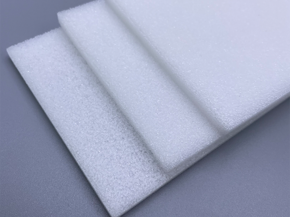
A plate filter design can work beautifully in compact manifolds, stacked assemblies, heat-integrated systems, large flat filtration panels, custom OEM skids, and applications where rectangular packaging fits better than cylindrical cartridges. Plates can integrate with gasketed frames, clamped packs, bolted manifolds, sintered sheets, mesh laminates, perforated supports, or diffusion structures.
Plates are good when the system needs controlled planar flow.
They are bad when gasket design is an afterthought.
Plate filters depend heavily on flatness, bolt load, gasket compression, frame stiffness, differential pressure support, thermal expansion, and cleaning access. Uneven compression creates bypass. Poor support creates bowing. Dirty gasket grooves create leaks. Wrong gasket material swells and ruins compression. Brownfield retrofits? Even worse, because old flange faces and field tolerances do not care about your pretty plate stack.
Plate geometry is not for casual purchasing.
Use it when you can control the manifold, compression, and service method. Avoid it when the installation crew will “make it fit” with uneven bolts and a prayer.
Pressure drop: shape changes the bill
A filter with the same media and micron rating can show different pressure drop because geometry changes effective area, flow distribution, entrance losses, support restriction, dead zones, and housing losses.
That’s the part catalog comparisons hide.
The U.S. Department of Energy’s pump-system efficiency study estimated about 20% potential energy savings in chemical-industry pumping systems through optimization, representing more than 7,500 GWh/year: DOE pumping system efficiency study. Filter geometry is part of that pressure-loss conversation. A bad geometry forces the pump to pay every hour.
And pressure drop is not only media resistance.
It is inlet path.
Outlet path.
Core restriction.
Manifold turns.
Support screens.
Pleat packing.
Dead zones.
Flow maldistribution.
The Irish EPA water filtration manual notes that cartridge and bag filters are designed with a maximum allowable pressure drop, called terminal pressure, and in practice filters are often replaced long before terminal pressure because flow decline makes continued use impractical: EPA Ireland water filtration manual. Geometry influences how quickly that pressure penalty arrives.
So don’t ask only, “What is the media ΔP?”
Ask, “What is the installed assembly ΔP at my flow?”
Huge difference.
How to Select Filter Geometry
Cartridge vs disc vs tube vs plate filter
Here is the clean comparison I’d use before committing to a drawing.
Geometry
Best fit
Main advantage
Main risk
Retrofit difficulty
My blunt recommendation
Cartridge
Standard housings, modular skids, water/process/gas filtration
Scalable area, easy replacement, common spares
Seal bypass, access clearance, long-element handling
Low to medium
Default choice unless the housing says otherwise
Disc
Compact OEM assemblies, vents, valves, regulators, small manifolds
Short axial length, simple shape, low profile
Face-seal leaks, uneven compression, deformation
Low if seat is controlled; high if not
Great in controlled seats, bad in sloppy cavities
Tube
Cleanable media, welded headers, gas/liquid process service, bundles
Strong cylindrical flow path, good for sintered media
Header bypass, vibration, uneven bundle loading
Medium to high
Use when flow distribution and removal are designed
Pleat blinding, media deformation, support collapse
Low to medium
Good when area is the bottleneck
Multi-tube bundle
Large process flow, high-temperature or cleanable service
High area inside one vessel
Harder inspection and tube balancing
High
Worth it only with serious header design
Sealing design: where “simple” filters fail
Sealing is where filter geometry becomes cruel.
A cartridge might use an O-ring, flat gasket, knife-edge seal, compression spring, threaded adapter, or bayonet lock. A disc might rely on axial compression. A tube may be welded or gasketed into a header. A plate may use a full-frame gasket. Each sealing method has a failure mode.
O-rings roll.
Flat gaskets creep.
Springs lose force.
Threads gall.
Welds crack.
Plate gaskets overcompress.
Operators install things backward.
That’s the field version.
Filter sealing design should be chosen before the quotation is finalized, not after the prototype leaks. Define gasket material—EPDM, FKM, PTFE, silicone, NBR, graphite, metal, whatever the chemistry and temperature require. Define compression. Define groove geometry. Define surface finish. Define whether the seal is product-contact. Define whether it can be inspected after installation.
I’m opinionated here: if the seal cannot be visually verified, keyed, or otherwise mistake-proofed, expect installation errors.
Not because technicians are careless.
Because plants are busy.
Manifold design: geometry is only half the story
A good filter element in a bad manifold becomes a bad filter system.
Filter manifold design decides whether flow reaches the media evenly. If the inlet jet hits one cartridge, that cartridge loads early. If a tube bundle has poor header distribution, some tubes do the work and others coast. If a plate stack has corner maldistribution, one zone blinds first. If the clean outlet creates a short path, bypass risk increases.
The 2024 experimental study on compressed-air filtration focused on lower-pressure-drop filter configurations instead of conventional selection: energy efficient compressed air filtration study. That study is about compressed air, not sintered cartridge selection, but the point travels well: configuration affects pressure drop. Geometry is not just the element shape; it is the way the system routes flow.
Ask these questions:
Where does flow enter?
Where does it leave?
Is velocity uniform?
Are there dead zones?
Can solids settle?
Can air be vented?
Can liquid be drained?
Can the clean side stay clean during service?
Can one element be isolated?
Can the manifold be flushed?
If not, your filter geometry may be solving one problem and creating five.
Retrofit feasibility: brownfield systems are mean
New skids are polite.
Old plants are not.
In brownfield work, geometry selection is often controlled by fixed housing diameter, nozzle position, floor space, pipe stress, crane access, cover swing, drain location, and what the operator can physically reach. I’ve seen engineers specify a cartridge that technically fit the housing but could not be removed because a cable tray sat above it. That drawing passed review. The maintenance crew did not.
Always check:
Element removal path.
Cover lifting clearance.
Tool access.
Drain/vent access.
Gasket replacement access.
Weight of wet element.
Disposal route.
Clean-side contamination risk.
Existing nozzle orientation.
Pressure-vessel rating.
A retrofit filter geometry that cannot be serviced safely is not a retrofit. It is a future shutdown.
Replacement access: design for the tired operator
This is where I get blunt.
If your design requires three hands, a special wrench, a clean-room-level attitude, and a flexible spine, the cartridge will be installed wrong eventually.
Cartridges should have clear orientation. Discs should have keyed seats if orientation matters. Tubes should be removable without bending. Plates should have guide pins and sane bolt patterns. Gaskets should not fall into the dirty chamber. Heavy elements should have handles, lifting points, or tools.
A filter element is not only installed by the engineer who designed it.
It is installed by a maintenance technician at the end of a shift, sometimes in gloves, sometimes in poor lighting, sometimes while production is calling every five minutes.
Design for that person.
How I’d choose geometry in real projects
I start with constraints, not preferences.
If the plant already has standard housings and wants easy spares, cartridge geometry wins. If the assembly is compact and OEM-controlled, disc geometry may win. If the system needs cleanable high-temperature or welded porous media, tube geometry becomes attractive. If the skid needs flat integration or custom flow paths, plate geometry may be worth the headache.
Then I ask:
Can it seal reliably?
Can it be removed?
Can it be cleaned?
Can it be inspected?
Can it handle pressure drop?
Can it scale surface area?
Can the manifold distribute flow?
Can the operator replace it without improvising?
That last question saves more money than people admit.
FAQ
What is filter geometry?
Filter geometry is the physical shape and layout of a filter element—such as cartridge, disc, tube or plate—that determines how it seals, fits into a housing, receives flow, creates pressure drop, allows replacement access, and integrates with manifolds, piping, supports, and service procedures.
It is not just appearance. Geometry affects hydraulic performance, maintenance safety, bypass risk, and retrofit feasibility.
How do you select filter geometry?
You select filter geometry by starting with the housing, flow path, sealing method, pressure drop limit, installation space, replacement access, manifold layout, process fluid, cleaning method, and retrofit constraints before choosing cartridge, disc, tube or plate construction.
Media selection matters, but geometry decides whether that media can actually work inside the system.
When should I use cartridge filter geometry?
Cartridge filter geometry should be used when the system needs modular replacement, standard housings, scalable surface area, common spare parts, and straightforward sealing for water, gas, oil, chemical, food, pharma, hydraulic, or general process filtration.
It is usually the safest default. But check axial clearance, seal alignment, weight, and removal access before approving the design.
When is disc filter design the best choice?
Disc filter design is best when the application needs a compact, low-profile filter element inside a controlled seat, such as a valve, regulator, vent, diffuser, analytical device, small manifold, or OEM assembly with limited axial space.
The weak point is face sealing. If compression, flatness, and gasket condition are not controlled, bypass can ruin the filtration claim.
When should engineers choose a tube filter element?
Engineers should choose a tube filter element when they need a cylindrical porous surface for cleanable filtration, welded headers, gas or liquid process service, high-temperature duty, sparging, venting, catalyst recovery, or multi-tube bundles inside a pressure vessel.
Tube filters work well when flow distribution, support, removal, and header sealing are engineered. They fail when manifold design is sloppy.
When does plate filter design make sense?
Plate filter design makes sense when a system needs flat packaging, stacked elements, custom manifold integration, planar flow control, rectangular footprint, or large filtration panels where cartridge or tube shapes do not fit the mechanical layout.
Plate designs require serious gasket, flatness, bolt-load, and support engineering. They are powerful but unforgiving.
How does filter geometry affect pressure drop?
Filter geometry affects pressure drop by changing effective surface area, face velocity, inlet and outlet losses, support restriction, manifold flow distribution, dead zones, core restriction, and how evenly the fluid reaches the filter media.
The same media can perform differently in different shapes or housings. Always ask for installed assembly pressure drop, not only media data.
What is the best filter geometry for retrofits?
The best filter geometry for retrofits is the one that fits existing housing dimensions, nozzle locations, removal clearance, sealing surfaces, drain and vent positions, pressure rating, maintenance access, and spare-part availability without unsafe field modifications.
In brownfield systems, the best hydraulic design may lose to installation reality. Check access before buying.
What is the difference between cartridge vs disc vs tube vs plate filters?
Cartridge filters are modular cylinders for standard housings, disc filters are compact flat elements for controlled seats, tube filters are porous cylinders for cleanable or bundled process service, and plate filters are flat or stacked elements for custom manifolds and planar layouts.
Each geometry has different sealing, pressure-drop, maintenance, and retrofit risks. The best choice depends on system constraints, not preference.
Procurement Guidance
Send us your housing drawing, flow rate, fluid type, pressure drop limit, material requirement, micron rating, sealing method, installation space, and replacement-access constraints. We’ll help you choose cartridge, disc, tube or plate filter geometry before the skid layout turns into a field modification.