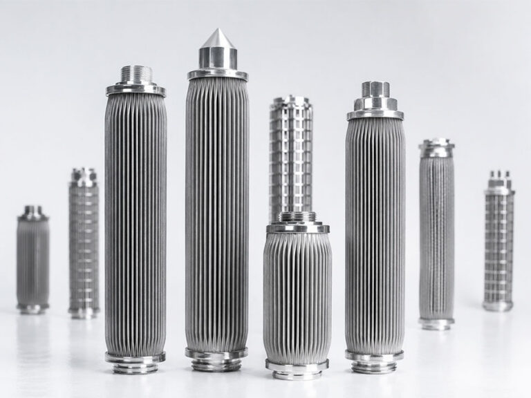
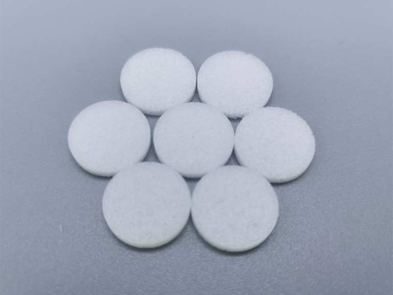
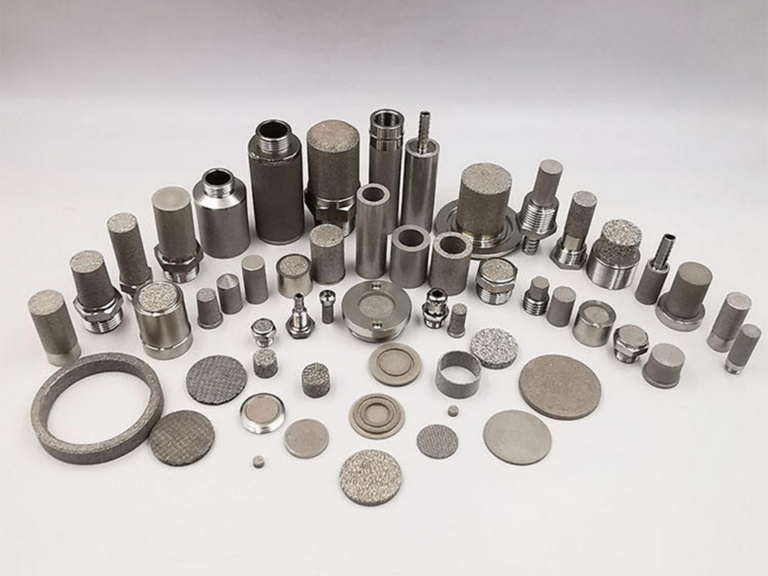
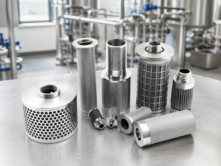
Before you leave, we invite you to talk directly with our managing team to ensure you receive the most accurate technical guidance, pricing support, and customization options for your project. Our experts can quickly evaluate your requirements, recommend suitable sintered plastic filter solutions, and help you reduce sourcing risks while improving efficiency, consistency, and long-term supply stability for your industrial applications.
Need Help Selecting the Right Filter Cartridge?
Our Sales Team
Tell our sales support team your product type, micron rating, size, application, filtered medium, working temperature, pressure, and estimated quantity. We will help you match the right sintered plastic, sintered metal, or sediment filter cartridge.
Flow Rate, Pressure Drop and Surface Area in Sintered Filters
Catalog flow curves lie.
Not always maliciously—but they lie by omission, because the neat little line on a supplier PDF usually assumes clean fluid, stable viscosity, standard temperature, one test gas or liquid, a fresh element, a specific pore grade, and no dirt cake forming inside the first hour of operation. Convenient, isn’t it?
I’ve watched engineers size housings from one “rated flow” number.
Bad move.
Sintered filter pressure drop is not a fixed property like length or thread size. It is a moving penalty charged by the filter when fluid tries to squeeze through a porous structure. Increase flow rate, pressure drop rises. Reduce surface area, pressure drop rises. Increase viscosity, pressure drop rises. Load particles into the pores, pressure drop rises again—sometimes slowly, sometimes like a bad stock chart.
And here’s the ugly truth: most filter sizing mistakes are not caused by bad filters. They’re caused by lazy assumptions.
Columbia University’s teaching material describes Darcy’s law as discharge rate being proportional to hydraulic gradient and hydraulic conductivity: Columbia University Darcy’s law explanation. USGS also treats Darcy’s law as the foundation of steady-state flow through porous media: USGS groundwater flow text.
For sintered filters, the simplified idea is this:
Flow increases when surface area and permeability increase.
Pressure drop increases when viscosity, flow velocity, media thickness, dirt loading, or restriction increases.
That sounds clean. It’s not.
Because a real sintered filter is not a neat bundle of straight holes. It’s a tortuous pore network. Powder particles, neck growth, pore throats, void volume, particle-size distribution, compression, and sintering temperature all shape the path. Fluid doesn’t march through. It negotiates.
Slowly, sometimes.
Angrily, often.
A rough Darcy-style relationship for liquid flow through porous media is:
ΔP ≈ μ × L × v / k
Where:
ΔP = pressure drop μ = dynamic viscosity L = filter media thickness v = superficial velocity k = permeability
Surface area enters through velocity. If the same flow rate is forced through less open filter area, velocity rises. Then pressure drop rises. The filter didn’t become “worse.” The sizing became worse.
Surface area: the cheapest pressure-drop reducer
Want lower sintered filter pressure drop?
Add area.
That answer sounds too simple, so people ignore it. They start arguing about micron rating, alloy, pleat geometry, powder grade, and pump curve before asking whether the element has enough effective surface area for the actual flow, viscosity, and solids load.
But surface area is the quiet lever.
A 10-inch cartridge and a 20-inch cartridge with the same media grade do not behave the same. A pleated sintered element can deliver more usable area than a plain cylinder. Multiple cartridges in parallel reduce face velocity. Larger diameter reduces velocity too. Lower velocity usually means lower clean pressure drop and slower dirt-cake loading.
Usually.
Here’s the catch: “surface area” on a catalog page may mean geometric area, not effective flow area. Dead zones, blocked end sections, weld margins, support structures, and bad housing design can steal area. I’ve seen housings where the element looked generous but the inlet flow slammed one side of the cartridge like a firehose. Local loading killed the filter early.
Not elegant.
Very common.
For OEM engineers doing porous metal filter sizing, I’d rather see a conservative area calculation with dirty-flow margin than a heroic design based on a clean lab curve.
Flow rate: rated flow is not process flow
A supplier says the filter handles 100 L/min.
Okay. With what fluid?
Water at 20°C? Air at standard conditions? Nitrogen? Hydraulic oil at 46 cSt? Solvent? Glycol? Hot polymer? Steam condensate with rust fines?
This is where catalog claims start getting slippery.
Flow rate in a sintered filter depends on fluid type, viscosity, density, temperature, pressure, gas compressibility, particle loading, and allowable pressure drop. For gases, standard liters per minute and actual liters per minute are not the same animal. For liquids, viscosity changes can wreck a design that looked fine in water testing.
Tiny example.
Water at 20°C has a dynamic viscosity near 1 mPa·s. A process oil can be 20, 50, or 100 times more viscous. If you size from water data and run oil through the same sintered media, don’t act shocked when the pressure drop climbs.
I’ve seen people blame the filter.
The math was guilty.
Pressure drop: clean ΔP, dirty ΔP, terminal ΔP
Pressure drop has stages.
Clean pressure drop is the starting penalty across a new or fully cleaned element. Dirty pressure drop is what happens as particles load into the surface cake and pore network. Terminal pressure drop is where the system says, “Enough.” That may be 1 bar, 2 bar, 5 psi, 15 psi, or whatever the pump, compressor, housing, seal design, or process can tolerate.
Mott’s porous metal refinery paper describes filtration operation as constant flow with increasing pressure drop until terminal pressure drop is reached: Mott porous metal filtration systems for petroleum refining. That line matters because many industrial systems are run at target flow, not target pressure. The system pushes harder until the filter plugs or the operator intervenes.
Hard truth: if your allowable ΔP window is narrow, your cartridge count needs to go up.
No magic media fixes undersized area.
And don’t confuse high collapse pressure with low pressure drop. A robust sintered stainless cartridge may survive high differential pressure, but that doesn’t mean your pump wants to pay that energy bill every hour.
Porosity and permeability: related, not identical
Porosity gets overused.
Permeability gets underchecked.
LibreTexts explains porosity as the ratio of void space to total material volume: LibreTexts 2024 Darcy’s law and porosity explanation. That’s useful, but porosity alone doesn’t tell the whole pressure-drop story.
Two filters can both show 40% porosity and behave differently.
Why?
Pore throat size. Tortuosity. Pore connectivity. Powder morphology. Sintering necks. Media thickness. Surface finish. Compaction. Dirt loading pattern. One filter may have large, well-connected pathways. Another may have many voids that don’t contribute much to through-flow.
Spintek’s porous metal guide puts it plainly: permeability is a measure of pressure drop at a given flow through a unit area, and porosity/permeability relationships are affected by powder size and forming method: porous metal design guidebook.
That’s why “high porosity” should not impress you by itself.
Ask for permeability.
Ask for clean ΔP at your flow.
Ask for test fluid.
Ask for media thickness.
Ask for actual cartridge geometry.
Pressure drop calculation for sintered filters
Use calculations to avoid stupid designs. Don’t use them as prophecy.
The U.S. NRC’s porous media pressure-drop document shows a Darcy equation form for viscous flow, Δp = μVL/K, and also references Ergun-type relationships for porous media: NRC porous media pressure drop calculation. For sintered filters, Darcy behavior is often a decent starting point at lower velocities, while inertial effects can matter at higher flow rates, especially in gases or coarse media.
A practical engineering sequence:
Define required flow rate.
Define fluid viscosity at operating temperature.
Define allowable clean ΔP and terminal ΔP.
Select micron rating based on particle target—not hope.
Estimate required media area.
Check supplier clean-flow data using the same or corrected fluid conditions.
Add fouling margin.
Confirm pump or compressor curve.
Test with real fluid if failure is expensive.
Skip step 9 only if downtime is cheap.
It usually isn’t.
For liquids, pressure drop tends to scale strongly with viscosity. For gases, density, compressibility, pressure basis, and standard-vs-actual flow can make sizing messier. For dirty service, particle loading can dominate everything after startup.
That’s where catalog curves stop being useful and pilot data starts earning its keep.
The surface-area trap in cartridge count
OEM engineers love compact housings.
I get it. Space is expensive. Stainless housings are expensive. Extra cartridges add cost, seals, inventory, and assembly time. But undersized housings create a different cost: pressure drop, energy use, short service life, unstable flow, and angry maintenance teams.
A single cartridge might technically pass the required clean flow.
Barely.
Then the process starts. Solids load. Viscosity shifts. Temperature drops. Differential pressure rises. The pump runs harder. The bypass valve gets blamed. Someone suggests a “better filter.” Procurement starts shopping.
No.
You needed more area.
From my experience, the best sizing conversations start with target clean ΔP and dirt-holding strategy, not just nominal micron rating. If the filter must hold flow for 30 days, size for 30 days. If it must survive compressor startup pulses, size for pulses. If it sees sticky particulate, don’t pretend it behaves like clean water.
The filter knows.
Comparison table: what really drives pressure drop
Variable
What happens when it increases
Impact on sintered filter pressure drop
Engineering warning
Flow rate
More fluid forced through same area
Pressure drop rises, often sharply at higher velocity
Rated flow without ΔP is nearly useless
Fluid viscosity
Fluid resists movement more
Pressure drop rises strongly
Water-test data can mislead oil or glycol systems
Filter surface area
Same flow spreads over more area
Pressure drop usually falls
Use effective area, not brochure area
Media thickness
Flow path gets longer
Pressure drop rises
Thick media may improve strength but costs ΔP
Permeability
Pore network allows easier flow
Pressure drop falls
Ask for test conditions, not just “high permeability”
Porosity
More void volume may help flow
Depends on pore connectivity
High porosity does not guarantee low ΔP
Dirt loading
Cake and pore blockage build up
Pressure drop rises over time
Terminal ΔP defines service life
Temperature
Changes viscosity and gas density
Can raise or lower ΔP
Size at worst-case operating temperature
Cartridge count
More elements share the flow
Pressure drop falls per element
Parallel area is often cheaper than pump pain
A sizing example engineers actually recognize
Say you need 120 L/min through a sintered stainless cartridge bank.
The clean water test curve says one cartridge can handle 120 L/min at an acceptable ΔP. Nice. But your actual fluid is 8 cP at startup, not 1 cP water. Your particle load is moderate. Your terminal pressure drop is limited because the upstream pump has no extra headroom. Also, the plant wants 4 weeks between maintenance stops.
One cartridge is not a design.
It’s a wish.
A safer approach might use three or four cartridges in parallel, lowering velocity through each element, reducing clean ΔP, slowing cake buildup, and giving the system margin when viscosity rises or particles load unevenly. Yes, the housing costs more. But the smaller housing was only cheaper before the first shutdown.
I know. Procurement hates that sentence.
Operations understands it immediately.
Where engineers get fooled
The first mistake is using nominal micron rating as if it predicts pressure drop.
It doesn’t.
A 10 µm sintered powder filter and a 10 µm sintered mesh filter may behave differently. A 5 µm porous metal tube and a 5 µm pleated sintered fiber element may have very different surface area and permeability. Same nominal rating. Different hydraulic behavior.
Second mistake: ignoring viscosity.
Third: treating gas flow as if standard flow and actual flow are interchangeable.
Fourth: forgetting dirt.
A clean element curve is a birth certificate, not a life story. The real story starts when solids, oil mist, rust, catalyst fines, polymer bits, or scale enter the media.
Fifth: trusting “maximum flow rate.”
Maximum according to whom? At what ΔP? For how long? With what fluid? At what temperature? Clean or loaded? Horizontal or vertical housing? Inside-out or outside-in? With what support tube?
Ask those questions and the room gets quieter.
Good.
FAQ
What causes pressure drop in sintered filters?
Pressure drop in sintered filters is caused by fluid resistance through the porous media, including viscosity, flow velocity, media thickness, permeability, pore structure, surface area, and dirt loading that blocks pore channels or builds a cake layer during operation.
In plain shop language, the filter is charging energy for forcing fluid through tiny connected passages. More flow, thicker media, higher viscosity, lower permeability, or less area means a higher bill.
How do you calculate pressure drop in sintered filters?
Pressure drop in sintered filters is commonly estimated with Darcy-style porous media relationships where ΔP depends on viscosity, media thickness, superficial velocity, and permeability, then corrected with real supplier test data, fouling margin, and gas or liquid operating conditions.
Use calculation as a screening tool. For expensive equipment, verify with the actual fluid, actual temperature, actual cartridge geometry, and realistic particle load.
How does flow rate affect sintered filter pressure drop?
Flow rate affects sintered filter pressure drop by increasing velocity through the available pore network; when the same filter area handles more flow, the resistance rises and the system needs more upstream pressure to maintain the target flow.
At low velocities the relationship may look close to linear. At higher velocities, especially with gases or coarse media, inertial effects can make the curve steeper.
How does surface area affect pressure drop in sintered filters?
Surface area affects pressure drop in sintered filters by spreading the same flow across more media, reducing superficial velocity through each pore region and usually lowering clean pressure drop, slowing dirt loading, and extending usable service life.
That’s why longer cartridges, larger diameters, pleated structures, or multiple cartridges in parallel often solve pressure-drop problems better than chasing a miracle media grade.
What is sintered filter permeability?
Sintered filter permeability is a measure of how easily fluid passes through the porous structure at a given pressure drop, flow rate, media thickness, and surface area, reflecting pore size, pore connectivity, tortuosity, and manufacturing method.
High porosity does not always mean high permeability. Connected pore pathways matter more than empty volume that doesn’t contribute to through-flow.
What is the difference between porosity and permeability?
Porosity is the percentage of void space inside a sintered filter material, while permeability describes how easily fluid can actually flow through those connected pores under pressure, making permeability more useful for predicting pressure drop and flow performance.
Two media can share the same porosity but show different pressure drop because pore throats, tortuosity, compaction, and sintering conditions differ.
How do I size a porous metal filter?
You size a porous metal filter by defining required flow, fluid viscosity, operating temperature, allowable clean and terminal pressure drop, particle loading, micron rating, cartridge geometry, and effective surface area before selecting media grade and cartridge count.
Don’t size from rated flow alone. Use flow curves, correction factors, fouling margin, and pilot testing when shutdown risk is expensive.
Why does pressure drop increase during operation?
Pressure drop increases during operation because particles, gels, rust, catalyst fines, scale, oil mist, or biological material accumulate on the filter surface and inside pore channels, reducing open flow paths and forcing the system to push harder to maintain flow.
A rising differential pressure trend is not just a maintenance number. It is the filter telling you how fast its usable void structure is disappearing.
Can a larger surface area reduce pump or compressor load?
A larger surface area can reduce pump or compressor load because it lowers velocity through the filter media, reduces clean pressure drop, slows dirt-cake formation, and helps keep the system away from terminal differential pressure for longer operating periods.
More area costs money upfront. Undersized area charges interest every hour through energy use, short service life, and downtime.
Procurement Guidance
Send us your required flow rate, fluid type, viscosity, operating temperature, allowable clean ΔP, terminal ΔP, micron rating, particle load, and housing limits. We’ll help you size sintered filter surface area, cartridge count, and media grade before the pump curve—and the maintenance team—start complaining.